Image Processing using GPU Accelerated Connected Component Labeling
Introduction
High performance image processing is the foundation of many applications
including machine vision, real time object recognition, security and many
other applications. One of the common processing steps in many of these
applications is connected component labeling (CCL). CCL is a simple, but
computationally intensive process.
CCL can be defined as identifying objects within a graph of elements which
have the same identifiable property and are connected.
A series of high resolution digital images will be provided. This challenge
is to process these high resolution images to identify all
objects/areas consisting of groups of adjacent pixels of the same color within
a specified threshold.
The implementation will be checked for correctness and total
performance.
Input
Each image will be given to you as a int[] in row-major order
(first pixel is upper left). Each pixel will be have its three color
channels encoded in a single integer. The lowest order 8 bits will give the
blue channel, the next highest 8 bits the green channel, and the next highest
8 bits the red channel. You will also be given W, the width
of the image.
Two other parameters will control how you find the connected components. The
first is degree_of_connectivity and indicates whether diagonal pixels
should be considered adjacent. If degree_of_connectivity is 4, then
only the 4 adjacent pixels should be considered adjacent. If it is 8, then
the diagonal ones should be considered adjacent also. Finally, a
int threshold will be provided. Two adjacent pixels are
considered to be connected if the sum of the differences in their color
components is not more than threshold. That is, if
|R1-R0| + |G1-G0| + |B1-B0| <= threshold
Output
You should return a int[] which is the same size as the input.
Each element should specify the index of the connected component that pixel is
in. The index of a connected component is the smallest pixel index (index
into the input array) of any pixel in that component.
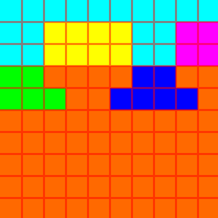
For example, consider the 10x10 image shown here:
 If the threshold were set to 300, and degree_of_connectivity were 4, we would decompose it into the 6 connected components shown here:
 The cyan one would have all its pixels labeled 0, since it's lowest indexed pixel is the upper left corner. The yellow component would have all its pixels labeled 12, since that is the index of the upper left corner of the yellow box. Moving to the end, the lowest index of the large orange region is 32. Note that if degree_of_connectivity had been 8, there would have only been two connected components.
Resources
Wikipedia has a comprehensive write up of connected component labeling at http://en.wikipedia.org/wiki/Connected_Component_Labeling.
This task uses a 2D mesh of connected pixels so the generalized case of CCL or
CCA of an arbitrarily connected graph does not have to be solved.
There have also been discussions about the use of NVIDIA CUDA Architecture for CCA in published papers and also on
NVIDIA
CUDA Developer forums.
An excellent, easy to follow, paper on the subject can be found at:
http://www.massey.ac.nz/~kahawick/cstn/089/cstn-089.pdf
In this paper, section 4 "Hypercubic Mesh Graphs" may be helpful.
Environment & Target Configuration
NVIDIA Tesla C1060 with 4GB of Global Memory
Intel Q8200 CPU
4GB of system memory
Centos 5.3 Linux
NVIDIA GeForce GPU for graphics
Your application should use NVIDIA CUDA 2.3 SDK.
gcc, g++, CUDA 2.3 drivers, tookit and SDK are installed on the servers, and
execution path and Library paths setup.
Testing and Scoring
Your score for each test case will be a 0 if you fail to return the right
answer, and otherwise will be your runtime in milliseconds. Your overall
final score will be the total number of pixels processed divided by your
total runtime in seconds. Note that the sum is taken before division is done,
giving more weight to larger test cases. Each incorrect answer (a 0 above) will halve your score, in addition to penalizing your total time 60 seconds.
| 
